Vibrionic Level Sensor
A Vibrionic level sensor is an advanced device used to measure the level of liquids and solids by detecting changes in the frequency of a vibrating probe. When the probe is immersed in a medium, its vibration frequency shifts, providing precise and reliable level measurements. These sensors are highly durable, with no moving parts, and are designed to perform accurately in harsh environments, including extreme temperatures and pressures. Ideal for industries such as chemical processing, food and beverage, and pharmaceuticals, Vibrionic level sensors ensure consistent operation and reduce maintenance needs.
Description
A Vibrionic level sensor measures the level of liquids and solids in various industrial applications. These sensors utilize vibrating probe technology to provide reliable and accurate level measurement. In addition, they suit challenging environments where traditional level measurement methods might struggle, such as in the presence of high temperatures, pressures, or varying densities.
Principle of Operation
The core principle behind the Vibrionic level sensor is the use of a vibrating probe or tuning fork that operates based on the principle of resonance. In addition, when the sensor’s probe vibrates, it changes frequency depending on whether it is immersed in a medium (liquid or solid) or exposed to air. The system detects this frequency shift and translates it into a level measurement.
How does the Vibrionic Level Sensor Work?
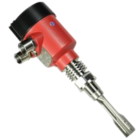
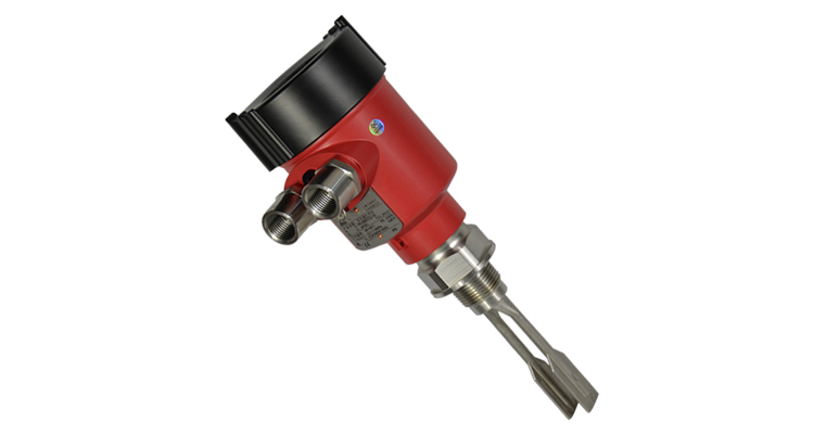
Vibration Probe: At the heart of the sensor is a vibrating probe or tuning fork. This probe vibrates at a specific frequency when not in contact with the medium. In addition, the probe’s physical properties and the medium around it determine the vibration frequency.
Detection of Phase Shift: When the probe is immersed in a liquid or solid, its vibration frequency changes. This is due to the added mass or density of the medium. In addition, the sensor’s electronics detect this change in frequency, known as phase shift.
Signal Processing: The electronics convert the detected phase shift into a signal that represents the level of the medium. In addition, the system processes the signal and transmits it to a display or control system, providing real-time level information.
Conclusion
The Vibrionic level sensor offers a robust and reliable solution for measuring levels of liquids and solids in various industrial applications. Also, their principle of operation, based on the detection of vibration frequency shifts, provides high accuracy and durability. With their ability to operate in harsh environments and handle a wide range of media, Vibrionic sensors are an invaluable tool for maintaining efficient and effective processes across multiple industries. Finally, proper installation, calibration, and maintenance are key to ensuring their optimal performance and longevity.
Other Level Sensors of Interest
Capacitive Level Sensor
Floating Level Sensor
Specifications
General Specifications
- Type: Vibrating probe level sensor
- Measurement Principle: Vibration frequency shift detection
- Applications: Liquids, solids, slurries
- Industries: Chemical, food and beverage, pharmaceuticals, oil and gas, water and wastewater treatment
Mechanical Specifications
- Probe Material: Stainless steel (304/316), Hastelloy, or other corrosion-resistant materials
- Probe Length: Customizable (typically ranges from 100 mm to 1000 mm)
- Probe Diameter: Standard sizes (e.g., 6 mm, 10 mm, 20 mm) or customized
- Mounting Type: Flanged, threaded, or clamp-on
- Mounting Orientation: Vertical, horizontal, or angled (depending on application requirements)
Electrical Specifications
- Power Supply:
- Standard: 24 V DC
- Optional: 110-240 V AC
- Output Signal:
- Analog: 4-20 mA
- Digital: Modbus, HART, or Profibus
- Protection Class: IP65, IP66, or IP67 (depending on model)
- Connection Type: Terminal block or cable gland
Performance Specifications
- Measuring Range:
- Minimum Level: 0 to 100 mm (adjustable based on application)
- Maximum Level: Up to 10 meters (customizable)
- Accuracy: ±1 mm to ±5 mm (depending on model and calibration)
- Resolution: 0.1 mm to 1 mm
- Response Time: Typically less than 1 second
- Medium Density Range: 0.5 to 10,000 kg/m³
Environmental Specifications
- Temperature Range:
- Operating: -40°C to +150°C (custom options available)
- Storage: -40°C to +85°C
- Pressure Range:
- Operating Pressure: Up to 50 bar (custom options available)
- Burst Pressure: Typically, 1.5 times the maximum operating pressure
- Chemical Compatibility: Compatible with a wide range of chemicals, including acids, bases, and solvents
Compliance and Certification
- Standards:
- CE (Conformité Européenne)
- UL (Underwriters Laboratories) – for applicable models
- ATEX or IECEx – for hazardous area applications (if required)
- Certifications: ISO 9001, ISO 14001 (for manufacturing quality and environmental management)
Additional Features
- Built-in Diagnostics: Self-diagnostics and error reporting
- Calibration: Easy calibration process with both manual and automatic options
- Temperature Compensation: Automatic compensation for variations in temperature
- Display: Optional local display for real-time monitoring and configuration
- Connectivity: Optional communication modules for integration with SCADA or DCS systems
Installation and Maintenance
- Installation:
- Mounting: Follow manufacturer’s guidelines for correct orientation and installation.
- Wiring: Connect according to provided wiring diagrams and instructions.
- Maintenance:
- Cleaning: Regular cleaning recommended based on application conditions.
- Calibration: Periodic calibration required to maintain accuracy.
Options and Accessories
- Extension Rods: For extended reach or custom installation needs
- Protective Coatings: For enhanced resistance to specific chemicals or harsh environments
- Heaters: For applications with very low temperatures
These specifications ensure that Vibrionic level sensors are versatile, reliable, and suitable for a wide range of industrial applications. Always refer to the manufacturer’s technical data sheets for specific model details and any additional options or customizations available.
Installation
Installation:
Probe Selection: Choose a probe length and material suitable for the application, considering factors like the type of medium, temperature, and pressure.
Mounting: Install the sensor in a vertical orientation to ensure accurate measurement. The probe should be fully immersed in the medium or positioned correctly to detect the level changes.
Wiring: Connect the sensor to the control system or display unit according to the manufacturer’s instructions. Ensure proper electrical connections and grounding.
Calibration:
Initial Calibration: Perform an initial calibration by setting the sensor to recognize the empty and full conditions of the vessel or tank. This involves adjusting the sensor’s settings to match the physical properties of the medium.
Periodic Calibration: Regularly check and recalibrate the sensor as needed to maintain accuracy. Calibration frequency depends on the application and environmental conditions.
Maintenance
Proper maintenance of Vibrionic level sensors is crucial for ensuring accurate measurements and prolonging the lifespan of the device. Follow these steps to maintain your Vibrionic level sensor effectively:
1. Regular Visual Inspections
- Frequency: Perform visual inspections at regular intervals, typically every 3 to 6 months, or as recommended by the manufacturer.
- Check for: Look for signs of physical damage, corrosion, or wear on the probe and housing. Ensure that the sensor is securely mounted and that there are no loose connections or leaks.
2. Cleaning the Sensor Probe
- Frequency: Clean the probe based on the nature of the medium and frequency of use, usually every 6 to 12 months, or more frequently if build-up is observed.
- Procedure:
- Turn Off Power: Ensure that the power supply to the sensor is turned off before cleaning.
- Remove the Probe: If possible, carefully remove the probe from the tank or process line. Refer to the manufacturer’s instructions for proper removal procedures.
- Clean the Probe: Use appropriate cleaning agents that are compatible with the medium and probe material. For many applications, a mild detergent and water solution may be sufficient. Avoid abrasive materials or harsh chemicals that could damage the probe.
- Rinse and Dry: Rinse the probe thoroughly with clean water and allow it to dry completely before reinstalling it.
3. Calibration
- Frequency: Calibrate the sensor as part of regular maintenance, typically every 6 to 12 months, or whenever the sensor is relocated or the medium changes.
- Procedure:
- Refer to Manufacturer’s Guidelines: Follow the specific calibration procedures provided by the manufacturer for your model.
- Set Calibration Points: Calibrate the sensor at both empty and full points of the vessel or tank. Use known reference levels for accurate calibration.
- Adjust Settings: Use the sensor’s control interface or software to adjust the calibration settings as needed.
4. Checking for Fouling or Build-Up
- Frequency: Inspect for fouling or build-up whenever the sensor is cleaned or during regular visual inspections.
- Procedure:
- Inspect Probe Surface: Check for any deposits or residues on the probe that could affect performance.
- Address Build-Up: If build-up is present, clean the probe thoroughly. For severe fouling, consider using a more intensive cleaning process or a chemical cleaner suitable for the application.
5. Electrical and Wiring Checks
- Frequency: Inspect electrical connections and wiring every 6 to 12 months.
- Procedure:
- Check Connections: Ensure that all electrical connections are secure and free of corrosion. Tighten any loose connections and replace any damaged wires.
- Inspect Insulation: Verify that insulation around the wiring is intact and not showing signs of wear or damage.
6. Testing and Diagnostics
- Frequency: Perform regular functional tests and diagnostics as recommended by the manufacturer, usually every 6 to 12 months.
- Procedure:
- Run Diagnostics: Use the sensor’s built-in diagnostic tools to check for any error codes or performance issues.
- Verify Accuracy: Test the sensor against known reference levels to confirm that it is providing accurate measurements.
7. Documentation
- Frequency: Maintain records of all maintenance activities.
- Procedure:
- Log Details: Record the date of inspections, cleaning, calibration, and any repairs or adjustments made. Include information on the medium being measured and any observed issues.
- Review Records: Regularly review maintenance logs to identify any recurring problems or trends that may require attention.
8. Training and Procedures
- Frequency: Ensure ongoing training for personnel responsible for maintaining the sensor.
- Procedure:
- Training: Provide training on proper maintenance procedures, safety protocols, and troubleshooting techniques.
- Update Procedures: Regularly update maintenance procedures based on new information or changes in operational requirements.
9. Safety Considerations
- Frequency: Follow safety guidelines during all maintenance activities.
- Procedure:
- Power Off: Always turn off the power supply to the sensor before performing maintenance.
- PPE: Use appropriate personal protective equipment (PPE) as required, especially when handling chemicals or working in hazardous environments.
- Lockout/Tagout: Follow lockout/tagout procedures if required to ensure that the equipment is safely isolated from power sources.
By adhering to these maintenance procedures, you can ensure that your Vibrionic level sensor continues to provide accurate and reliable performance, minimizing downtime and maintaining operational efficiency.
Q&A
Q1: What is a Vibrionic level sensor?
A1: A Vibrionic level sensor is a device that measures the level of liquids and solids using a vibrating probe. The sensor detects changes in the probe’s vibration frequency caused by the presence of the medium, which allows for accurate level measurement.
Q2: How does a Vibrionic level sensor work?
A2: The sensor’s probe vibrates at a specific frequency when not in contact with the medium. When the probe is immersed in the liquid or solid, the vibration frequency changes due to the added mass or density of the medium. This frequency shift is detected and converted into a level measurement by the sensor’s electronics.
Q3: What are the main advantages of using Vibrionic level sensors?
A3: Vibrionic level sensors offer several benefits, including high accuracy, reliability, and durability. They have no moving parts, making them low-maintenance and suitable for harsh environments. They are also versatile, capable of measuring both liquids and solids, and resistant to high temperatures and pressures.
Q4: In which industries are Vibrionic level sensors commonly used?
A4: Vibrionic level sensors are commonly used in industries such as chemical processing, food and beverage, pharmaceuticals, oil and gas, and water and wastewater treatment. They are ideal for applications where accurate level measurement is crucial and where harsh operating conditions are present.
Q5: How should a Vibrionic level sensor be installed?
A5: To install a Vibrionic level sensor, select a probe length and material suited to the application. Mount the sensor in a vertical orientation to ensure accurate measurement and connect it according to the manufacturer’s wiring diagram. Ensure the probe is properly immersed in the medium or positioned to detect level changes.
Q6: What maintenance is required for Vibrionic level sensors?
A6: Maintenance typically involves regular visual inspections for signs of wear or damage, cleaning of the probe to prevent build-up, and periodic calibration to ensure measurement accuracy. It’s also important to check for any fouling or interference that could affect sensor performance.
Q7: Can Vibrionic level sensors handle extreme temperatures and pressures?
A7: Yes, Vibrionic level sensors are designed to operate in extreme temperatures and pressures. However, it is important to select a sensor with specifications that match the specific conditions of your application to ensure optimal performance.
Q8: What should be done if the sensor readings are not accurate?
A8: If the sensor readings are not accurate, check for issues such as probe fouling, incorrect calibration, or installation problems. Perform a recalibration and clean the probe if necessary. Consult the manufacturer’s troubleshooting guide for specific issues related to your sensor model.
Advantages / Disadvantages
Advantages
Accuracy and Reliability: Vibrionic level sensors provide precise and reliable measurements across a wide range of applications. They are less affected by changes in the physical properties of the medium, such as density and viscosity, compared to other types of level sensors.
No Moving Parts: Unlike mechanical level sensors, Vibrionic sensors do not have moving parts that can wear out or require maintenance. This makes them more durable and reduces the need for frequent servicing.
Versatility: These sensors can measure both liquid and solid levels, making them suitable for a variety of applications, including those involving powders, granules, and slurries.
Resistance to Harsh Environments: Vibrionic level sensors are designed to operate in harsh environments. They are resistant to high temperatures, pressures, and aggressive chemicals, making them ideal for challenging industrial conditions.
High-Accuracy Measurement: The use of vibration frequency shifts provides high accuracy in level measurement, even in complex or difficult-to-measure environments.
Challenges and Considerations
Build-Up and Fouling: In some applications, the sensor probe may experience build-up or fouling, which can affect measurement accuracy. Regular cleaning or maintenance may be required to address this issue.
Temperature and Pressure Extremes: Although Vibrionic sensors are designed to withstand harsh conditions, extreme temperatures and pressures can still impact their performance. Ensure that the sensor specifications match the operating conditions of the application.
Medium Characteristics: The characteristics of the medium, such as density and viscosity, can influence sensor performance. Choose a sensor with the appropriate sensitivity and range for the specific medium.
Applications
Chemical Industry: In the chemical industry, Vibrionic level sensors are used to measure the levels of corrosive and reactive chemicals in tanks and vessels. Their resistance to harsh chemicals and high temperatures makes them ideal for this application.
Food and Beverage Industry: These sensors are employed to monitor the levels of ingredients, products, and by-products in food processing and beverage production. They ensure consistent quality and prevent overflows or shortages.
Pharmaceutical Industry: In pharmaceutical manufacturing, maintaining precise levels of liquids and powders is critical. Vibrionic level sensors provide accurate measurement to ensure product consistency and compliance with regulations.
Oil and Gas Industry: Vibrionic sensors are used to measure levels in oil and gas production and refining processes. Their ability to operate under high pressures and temperatures makes them suitable for this demanding environment.
Water and Wastewater Treatment: These sensors help monitor the levels of water and sludge in treatment facilities. They play a crucial role in managing and optimizing the treatment processes.
Drawings