
Understanding Motor Inrush Currents, & NEC Article 430.52
Understanding Motor Inrush current, or “locked rotor current,” is the excessive Understanding of Motor Inrush current flow. A motor and its conductors experience this during the first few moments. This is following the energizing (switching on) of the NEMA motor. This current draw is sometimes referred to as “locked rotor current”. This is because the current is necessary at startup to begin the rotation of a non-rotating. Also, the de-energized NEMA motor shaft is very similar to the extreme current draw experienced. This is the moment when a motor overloads to the point of seizing. In both cases, the motor draws the same current required to overcome an idle motor shaft.
Over-Current Device
The over-current devices protecting the NEMA motor, and its circuitry must be able to withstand this brief. Also, but extreme current spike, while still providing appropriate protection against short-to-ground faults and motor overload conditions.
This can be a fine line to walk.
Understanding Motor Inrush Current is a Necessary Overload Condition
So, what is motor inrush-current? When an AC NEMA motor is first energized, excessive current is drawn on the circuit supplying the motor, well beyond the current levels specified on the motor nameplate. When starting a motor from a static (idle) position, you often encounter high resistance, and the motor requires excessive current to begin rotating the shaft.
Often, during the initial half-cycle of electrical current flow experienced at motor startup, (Note: A half-cycle in a 60 Hz electrical system equates to 1/120 of a second duration of time) inrush currents reach levels 20 times greater than the normal current levels experienced during the motor’s normal operating speeds. After this initial understanding of motor inrush current, the motor begins to rotate. At this point the initial starting current subsides, reducing to a level of current. This is equal to 4 – 8 times the normal running current for that motor. The motor sustains this reduced, yet still largely exaggerated, current only briefly. Furthermore, as the motor quickly reaches full running speed, the current subsides to its normal operating level.
Understanding Motor Inrush Current and the Motor Components
When considering or Understanding Motor inrush current, it helps to understand what is going on inside the AC induction motor when we first energize it. We know that power instantly energizes the stator windings upon startup. The alternating current (AC) supplied to this winding, produces an alternating magnetic field and then induces that field into the rotor.
The difference in the magnetic fields between the stator winding (a stationary copper winding group within the motor). Finally, the rotor winding (rotating shaft winding) is the biggest contributor to the initial Understanding of Motor inrush current experienced at startup. Once the rotor starts to rotate and then catches up with the stator’s magnetic field. As a result, the diminishing difference between the two fields reduces the inrush current proportionally.
Of course, we know the standard AC induction motor always experiences some degree of slip; the two magnetic fields never synchronize entirely, as the rotor always lags the stator winding field to some degree. We specify this motor ‘slip’ as the percent of slip, and the final torque delivered from the motor shaft results from the magnetic force induced to the shaft, minus the slip.
Protection of Motor Circuits
The National Electrical Code requires several levels of protection when it comes to installing motor control systems. This protection is necessary for the motor’s feeder circuit, (short circuit and ground-fault protection). Also, the motor’s branch circuit (short circuit and ground-fault protection) as well as motor overload protection. This is where we measure the current flow to the motor at each phase of the circuit supplying the motor assembly.
Understanding the potential for motor starting-current (in-rush current), in addition to the motor’s nameplate voltage rating. Also, the horsepower(hp) rating, and full-load-amp (FLA) rating, in conjunction with the NEC. This gives us the information needed to properly size the overcurrent/overload protection for that motor.
We want the OCPD (over-current-protection device), whether it be a circuit breaker or fuse. This is to provide maximum protection against shorting and overload conditions. We also need these protective devices to ignore, for a short period. The motor will inevitably experience in-rush current during startup.
Inverse Time Breakers and Fuses
Inverse time circuit-breakers and time-delay fuses, made available for use by permission found in 430.52 of the NEC, make this short-to-ground protection, coupled with a blind eye to overload possible. Both the inverse-time circuit breaker and the time-delay fuse are designed to endure massive inrush currents for the few hundredths of a second needed to get past the motor’s initial startup. Inverse-time breakers achieve this by using an attribute called the ‘trip-curve,’ which allows extreme, exaggerated current to remain on the breaker for up to half a second or longer, while still instantly tripping the breaker contacts when detecting an outright short-to-ground current flow.
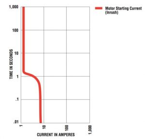
Table 430.52 provides the increase of fuse or circuit-breaker ampacity, ranging from 225% to 400% of the circuit rating. It does little to resist the inrush above the current. However, this allowed an increase in overcurrent device (breaker or fuse) size. This maintains the circuit during the few seconds immediately following that initial inrush current. Furthermore, as the current subsides and winds down to a normal operating current.
You can find the built-in delay properties within these two types of overcurrent devices, along with the allowed increase in size for these devices as permitted in T430.52. This makes it possible for the motor branch circuit to endure the momentary bombardment of extreme inrush currents experienced at motor startup.
Correct selection for CB protection.
For standard short-circuit protection using an inverse time circuit breaker, we use the following:
- Use tables 430.247 and 430.250 to determine the motor FLC. (Note we do not use the motor nameplate information).
- From Table 430.52 we find the correct maximum setting value for standard short-circuit protection
- We multiply the motor FLC by the value in Table 430.52
- We round up the nearest standard rating available in Table 240.6(A).
Under Code-section 430.52(C)(1)(c), we find an exception to the permission(s) granted for sizing an inverse time circuit-breaker, located in Table 430.52. We read: Where the circuit-breaker rating determined by T430.52 is not sufficient. Not sufficient for the starting current (inrush current) experienced by the motor. The electrician is allowed to increase the circuit-breaker size even further, up to a maximum of 400%. This is for loads that do not exceed 100 amps. And up to a maximum of 300% for loads that are greater than 100 amps.
Fuses Used in Place of Circuit-Breakers
Concerning fuses being selected as the overcurrent device, instead of the inverse-time circuit-breaker. We still use Table 430.52 for initial sizing, but there are additional and more restrictive rules that exist for the upsizing of these fuses beyond the Table, to overcome inrush current. These additional rules and restrictions are found in Code-section 430.52(C)(1).
By: Stan Turkel | Mar 05, 2019, Understanding Motor Inrush 2017 National Electrical Code