Description
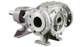
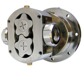
Thermal Oil Pumps (also known as Hot Oil Pumps or Heat Transfer Fluid Pumps) are heavy-duty centrifugal pumps specifically engineered to circulate thermal oils and heat transfer fluids at high temperatures.
They enable precise, efficient heating in closed-loop systems without the high pressure and safety concerns associated with steam.
These pumps are built to handle extreme thermal expansion, viscosity changes, and the risk of fluid vaporization while maintaining reliable, leak-free performance.
Types of Thermal Oil Pumps
| Type |
Description |
Key Characteristics |
| Standard Centrifugal |
Traditional single-stage or multi-stage centrifugal pumps with mechanical seals and external cooling systems. |
Cost-effective; requires regular seal maintenance; suitable for moderate temperatures. |
| Magnetic Drive (Sealless) |
Uses magnetic coupling to drive the impeller without a shaft seal. Ideal for hazardous or high-temperature fluids. |
Zero leakage; lower maintenance; slightly reduced efficiency due to magnetic losses. |
| Canned Motor |
Motor and pump are integrated in a single hermetically sealed unit. The pumped fluid cools the motor. |
Completely leak-proof; compact; excellent for very high temperatures and toxic fluids. |
| Air-Cooled / Water-Cooled |
Standard centrifugal pumps with specialized bearing housings that use air fins or water jackets for cooling. |
Widely used; good balance of cost and performance; requires external cooling medium in some cases. |
Main Components & Their Functions
| Component |
Function in Thermal Oil Service |
| Impeller |
Converts mechanical energy into kinetic energy of the fluid. Usually open or semi-open design to handle thermal expansion and any solids. |
| Volute Casing |
Converts velocity into pressure. Self-venting design helps remove vapor bubbles formed at high temperatures. |
| Shaft & Bearings |
Transmits torque. Special high-temperature bearings (graphite, silicon carbide) with cooling systems to protect against heat. |
| Mechanical Seal / Magnetic Coupling |
Prevents leakage. High-temperature seals or sealless magnetic drive systems are critical for safety and reliability. |
| Cooling System |
Air fins, water jacket, or thermal barrier that protects the bearings and motor from conducted heat. |
| Motor |
Drives the pump. Often oversized or with special cooling to handle continuous high-temperature duty. |
Detailed Operation Process
| Step |
Operation Description |
| Startup |
Pump is primed with thermal oil. Cooling system (air or water) is activated. Motor starts and accelerates the impeller gradually to avoid thermal shock. |
| Fluid Circulation |
Impeller rotates at high speed, imparting centrifugal force to the oil. Oil flows from suction to discharge while absorbing heat from the process equipment. |
| Heat Management |
Heat from the hot oil is transferred through the casing and shaft. The cooling system continuously removes this heat to protect bearings and seals. |
| Vapor Handling |
Any vapor bubbles formed due to local boiling are vented through the self-venting volute or recirculation lines back to the expansion tank. |
| Continuous Operation |
Pump maintains steady flow and pressure. Temperature is monitored closely; thermal expansion of components is accommodated by flexible couplings and design clearances. |
| Shutdown |
Motor is stopped gradually. Cooling continues for a period to allow safe cooldown and prevent thermal shock or oil degradation. |
Key Design Features for High-Temperature Service
| Feature |
Purpose & Benefit |
| Thermal Barrier / Heat Shield |
Reduces heat transfer from the hot fluid to the bearings and motor, allowing standard motors to be used. |
| Air-Cooled or Water-Jacketed Bearing Housing |
Actively cools the bearings to maintain proper lubrication and prevent premature failure at temperatures above 200°C. |
| Extended or Centerline Mounting |
Accommodates significant thermal expansion of the pump casing without stressing the piping or foundation. |
| Special High-Temperature Bearings |
Graphite, silicon carbide, or specially lubricated bearings that can operate with reduced lubrication at high temperatures. |
| Self-Venting Volute & Recirculation Lines |
Removes vapor and gases that form when thermal oil approaches its boiling point, preventing cavitation and vapor lock. |
| Low NPSH Design |
Minimizes the risk of cavitation caused by reduced fluid viscosity and vapor pressure at high temperatures. |
Typical Operating Parameters
| Parameter |
Typical Range |
| Operating Temperature |
Up to 350°C (standard) / up to 400°C+ (special synthetic oils and designs) |
| Flow Rate |
5 – 2,000 m³/h (depending on pump size) |
| Head / Differential Pressure |
Up to 150–200 m (higher in multi-stage designs) |
| Viscosity Range |
Handles fluids from 1 cP up to several hundred cP (viscosity decreases significantly with temperature) |
| Maximum Pressure |
Typically 16–40 bar (higher pressure ratings available) |
Specifications
| Parameter |
Standard Range / Specifications |
Notes |
| Pump Type |
Horizontal centrifugal (single or multi-stage), magnetic drive, or canned motor |
API 610 / ISO 5199 compliant options available |
| Capacity (Flow Rate) |
5 – 2,000 m³/h |
Higher flows on request |
| Head |
Up to 160 m (single stage) / up to 300 m (multi-stage) |
Custom impellers for specific duty points |
| Operating Temperature |
–20°C to +350°C (standard) / up to +420°C (special designs) |
Depends on thermal fluid type |
| Design Pressure |
PN16 / PN25 / PN40 (up to 50 bar) |
Higher pressure ratings available |
| Materials of Construction |
Cast steel (1.0619 / WCB), Stainless Steel (1.4408 / CF8M), Duplex, High-temp alloys |
Impeller & casing in heat-resistant materials |
| Shaft Sealing |
High-temp mechanical seals, Magnetic drive (sealless), or Canned motor |
API 682 seal plans available |
| Bearing System |
Oil-lubricated or grease-lubricated with air/water cooling |
Graphite or SiC radial bearings for sealless models |
| Motor Power |
0.75 kW to 500 kW (IEC or NEMA standards) |
Explosion-proof (ATEX / IECEx) options |
| NPSH Required |
Low NPSHr designs (1.5 – 6 m) |
Optimized to prevent cavitation at high temperatures |
| Efficiency |
Up to 82% (depending on operating point) |
Magnetic drive models slightly lower |
| Flange Connections |
DN32 to DN400 (ANSI / DIN / JIS standards) |
Raised face or flat face flanges |
| Viscosity Range |
0.5 – 500 cSt at operating temperature |
Performance curves adjusted for viscosity |
| Certifications |
CE, ATEX, ISO 9001, API 610, EAC, PED |
Custom certifications on request |
Specifications may vary by manufacturer and model. Custom-engineered solutions available for extreme duties.
Pump Comparisons
| Feature / Parameter |
Standard Centrifugal (Sealed) |
Magnetic Drive (Sealless) |
Canned Motor |
| Leakage Risk |
Medium (mechanical seal) |
Zero |
Zero |
| Max Temperature |
Up to 350°C |
Up to 400°C |
Up to 420°C |
| Maintenance |
Higher (seal replacement) |
Low |
Very Low |
| Efficiency |
Highest (78–85%) |
Slightly lower (72–80%) |
Moderate (70–78%) |
| Initial Cost |
Lowest |
Medium |
Highest |
| Noise & Vibration |
Standard |
Low |
Very Low |
| Suitability for Hazardous Fluids |
Good (with double seals) |
Excellent |
Best |
| Power Range |
Wide |
Medium to High |
Low to Medium |
| Cooling Requirement |
Air or Water |
Air or Water |
Fluid-cooled (process fluid) |
| Typical Applications |
General high-temp circulation |
Toxic / expensive fluids |
Critical / explosive environments |
Selection depends on temperature, fluid properties, safety requirements, and budget.
Installation Procedures
Proper installation is critical for safe, reliable, and long-term performance of high-temperature thermal oil pumps.
Pre-Installation Checklist
| Item |
Requirement |
| Foundation |
Level, rigid concrete foundation with anchor bolts. Must withstand vibration and thermal expansion. |
| Piping Alignment |
Suction and discharge piping must be independently supported. No stress on pump flanges. |
| Expansion Tank |
Installed at highest point with proper venting and nitrogen blanketing (if required). |
| Cooling System |
Air or water cooling lines connected and tested before startup. |
| Electrical |
Motor wired per nameplate, proper grounding, and overload protection installed. |
Step-by-Step Installation Procedure
| Step |
Procedure |
Important Notes / Safety |
| 1 |
Position the pump on the foundation and align using laser or dial indicators (max 0.05 mm misalignment). |
Do not use pump as pipe support. |
| 2 |
Install flexible couplings and guards. Check coupling alignment with pump and motor at ambient temperature. |
Re-check alignment after piping and hot oil filling. |
| 3 |
Connect suction and discharge piping with proper gaskets suitable for high temperature. |
Install strainers on suction side. Ensure NPSH availability. |
| 4 |
Connect cooling water/air lines and thermal insulation on hot surfaces. |
Cooling must operate before and after pumping hot oil. |
| 5 |
Fill the system with thermal oil slowly. Vent air from pump casing and piping. |
Use clean, dry oil. Avoid contamination. |
| 6 |
Prime the pump and turn the shaft by hand to ensure free rotation. |
Never run dry. |
| 7 |
Perform electrical checks, then start the pump briefly (bump test) to verify rotation direction. |
Correct rotation is critical for centrifugal pumps. |
| 8 |
Gradually bring the system to operating temperature while monitoring vibration, noise, and leakage. |
Allow thermal expansion to stabilize. Re-align if necessary. |
Safety Note: Always wear appropriate PPE. Follow lockout/tagout procedures. Installation must be carried out by qualified technicians familiar with high-temperature systems. Consult the manufacturer’s manual for model-specific instructions.
Maintenance Procedures
Regular maintenance ensures long service life, high reliability, and safe operation of high-temperature thermal oil pumps.
Preventive Maintenance Schedule
| Interval |
Activities |
| Daily |
Check for unusual noise/vibration, oil leaks, bearing temperatures, and cooling system operation. |
| Weekly |
Inspect coupling alignment, foundation bolts, and pressure gauges. Check thermal oil level and quality. |
| Monthly |
Lubricate bearings (if grease type), clean cooling fins, inspect seals and gaskets. |
| Every 6 Months |
Perform vibration analysis, check impeller wear, and test motor insulation resistance. |
| Annually / 8,000 hours |
Full overhaul: replace bearings, mechanical seals (if applicable), inspect wear parts, and flush system. |
Step-by-Step Maintenance Procedures
| Step |
Procedure |
Safety & Best Practices |
| 1 |
Lockout/Tagout the pump and isolate from the system. Allow complete cooldown below 50°C. |
Never work on hot pumps. Drain thermal oil safely. |
| 2 |
Drain oil from pump casing and bearing housing. Remove coupling guard and disconnect coupling. |
Collect and dispose of oil according to environmental regulations. |
| 3 |
Inspect and clean cooling fins, heat exchanger, and thermal barrier. Check for blockages. |
Proper cooling is essential for bearing life. |
| 4 |
For sealed pumps: Replace mechanical seal and seal flush lines. For magnetic drive: Inspect containment shell and magnets. |
Use manufacturer-recommended seal kits only. |
| 5 |
Replace bearings and check shaft runout. Lubricate as per specification (grease or oil). |
Use high-temperature lubricants only. |
| 6 |
Inspect impeller, wear rings, and volute for erosion or corrosion. Balance impeller if required. |
Clearance must match manufacturer tolerances. |
| 7 |
Reassemble, realign coupling, and perform rotation test by hand. |
Ensure no binding. |
| 8 |
Refill with fresh filtered thermal oil, vent air, and perform commissioning run while monitoring parameters. |
Monitor temperature, vibration, and current draw during startup. |
Important: Always follow the manufacturer’s specific maintenance manual. Use genuine spare parts. Record all maintenance activities. High-temperature thermal oil can degrade – test oil condition regularly for acid number, viscosity, and flash point.
Q&A
| Question |
Answer |
| What is the maximum temperature a thermal oil pump can handle? |
Standard models handle up to 350°C. Special high-temperature versions with synthetic oils and advanced cooling can reach 400–420°C. |
| Why is cooling necessary for thermal oil pumps? |
Cooling systems (air or water) protect bearings and seals from excessive heat conducted from the hot oil, preventing premature failure and maintaining proper lubrication. |
| What is the advantage of magnetic drive thermal oil pumps? |
They are completely sealless, offering zero leakage — ideal for toxic, expensive, or hazardous thermal fluids while reducing maintenance. |
| How often should thermal oil be changed? |
Typically every 1–3 years depending on operating temperature, oxidation level, and oil analysis results (acid number, viscosity, flash point). |
| Can thermal oil pumps run dry? |
Short periods (a few minutes) may be possible with special bearing designs, but prolonged dry running is not recommended and can cause severe damage. |
| What causes cavitation in thermal oil pumps? |
High fluid temperature increasing vapor pressure or insufficient NPSH. Low-NPSH designs and proper system venting help prevent this. |
| Do I need special alignment procedures for hot oil pumps? |
Yes. Alignment should be checked at ambient temperature and re-verified after the system reaches operating temperature due to thermal expansion. |
| What materials are typically used? |
Cast steel or stainless steel casings, high-temperature impellers, and special bearings (graphite or silicon carbide) for reliability at elevated temperatures. |
| How do I choose between sealed, magnetic drive, and canned motor pumps? |
Choose based on fluid hazard level, temperature, maintenance preference, and budget. Magnetic drive or canned motor for zero-leakage critical applications. |
| What safety features should be installed? |
Temperature sensors, vibration monitoring, low-flow protection, pressure relief valves, and emergency shutdown systems. |
Have more questions? Feel free to ask for model-specific recommendations.
Advantages / Disadvantages
| Advantages |
Disadvantages |
- Excellent temperature control up to 420°C without high pressure
- Lower operating pressure compared to steam systems (safer)
- Uniform and efficient heat distribution in closed loops
- Sealless (magnetic drive) options for zero leakage
- Long service life with proper maintenance
- Wide range of flow and head capabilities
- No risk of freezing or scaling like water-based systems
|
- Higher initial purchase cost than standard pumps
- Requires specialized cooling systems (air/water)
- Thermal oil degrades over time and needs periodic replacement
- Lower efficiency compared to water pumps due to fluid properties
- Sensitive to NPSH and vapor formation at high temperatures
- Requires careful alignment due to thermal expansion
- More complex maintenance for bearings and seals
|
Thermal oil pumps are ideal when precise high-temperature control and safety are priorities, but system design and maintenance must be carefully planned.