Description
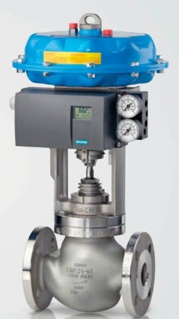
Modulating control valves play a vital role in regulating the flow of fluids in industrial processes by continuously adjusting the valve position to maintain precise control over the flow rate. These valves allow for gradual adjustments to the flow rate, making them essential for applications requiring accurate and dynamic control.
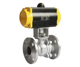
I/P (current to pressure) positioners are commonly used with modulating control valves to convert electrical signals into pneumatic signals that position the valve accordingly. These positioners ensure that the valve responds accurately to control signals, enabling precise flow control in response to changing process conditions.
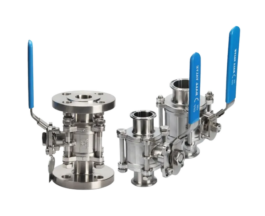
Modulating control valves come with different connection end options to suit various piping systems. FNPT (Female National Pipe Thread) connections provide threaded ends for easy installation into female threaded pipes or fittings. Flanged connections feature bolted flanges that provide a secure attachment to flanged pipes or equipment, ensuring a leak-proof seal. Sanitary Tri-clamp connections are designed for applications where cleanliness and easy disassembly are essential, common in industries such as food and pharmaceuticals.
Materials play a crucial role in the construction of modulating control valves to ensure durability and performance in demanding environments. Carbon steel valves are known for their strength and durability, making them suitable for applications with moderate pressure and temperature conditions. Stainless steel valves, including various grades like 304 and 316 stainless steel, offer excellent corrosion resistance, making them ideal for applications where exposure to corrosive substances is a concern. Stainless steel valves are particularly desirable in industries such as chemical processing, pharmaceuticals, and food and beverage, where sanitation and resistance to harsh chemicals are essential.
In summary, modulating control valves are essential for precise flow control in industrial processes, with I/P positioners enhancing their functionality. The choice of connection ends, such as FNPT, flanged, or sanitary Tri-clamp options, depends on installation requirements and industry standards. Materials like carbon steel and stainless steel are selected based on factors like strength, corrosion resistance, and environmental conditions to ensure optimal performance and longevity of modulating control valves in a wide range of industrial applications.