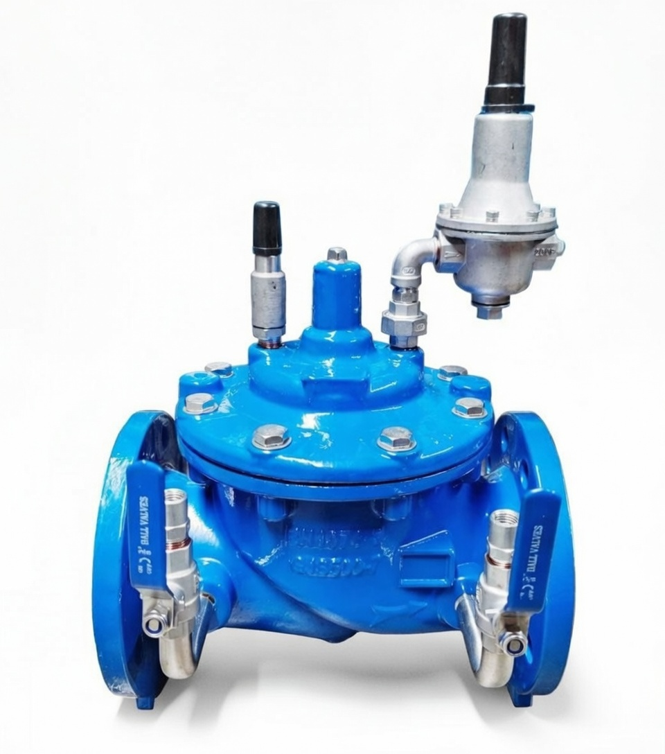
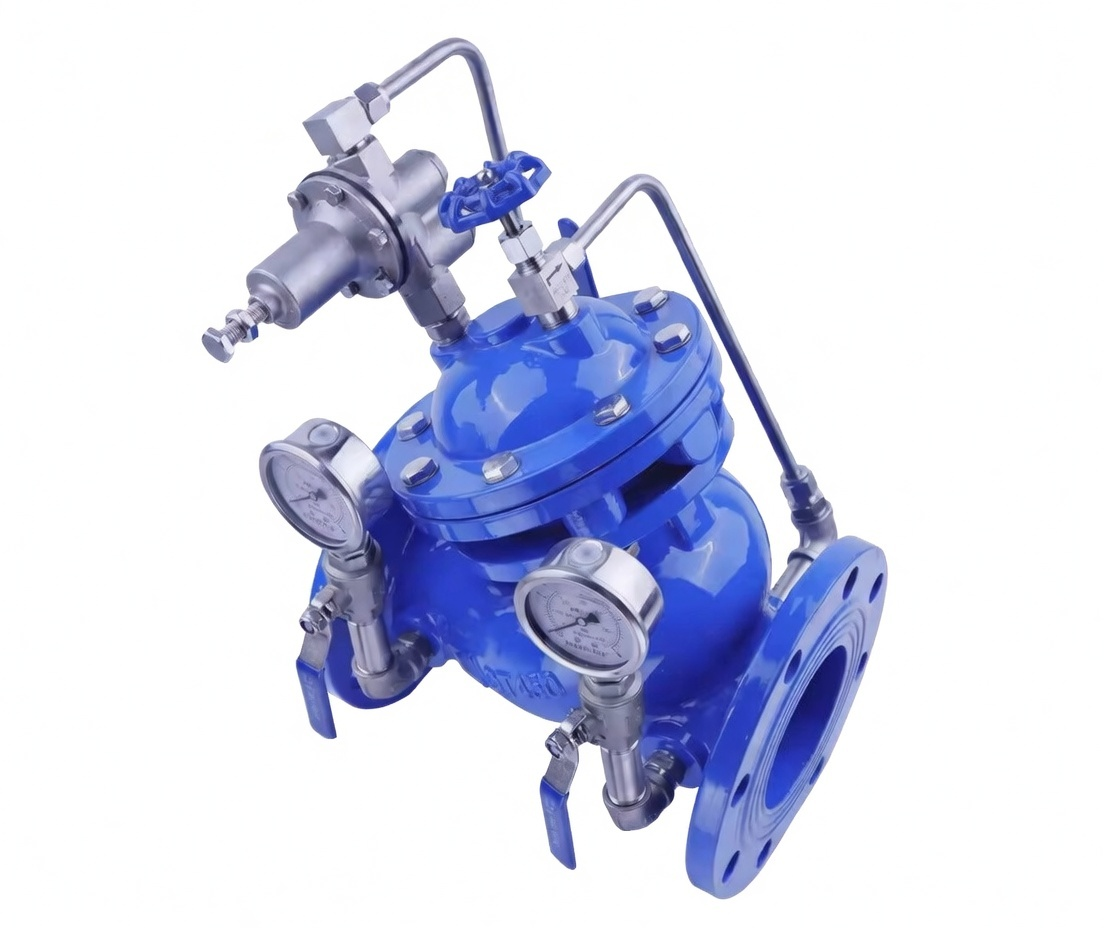
Pilot Operated Hydraulic Control Pressure Reducing Valve

Pilot Operated Hydraulic Control Pressure Reducing Valve

Category Key Features Technical Specifications
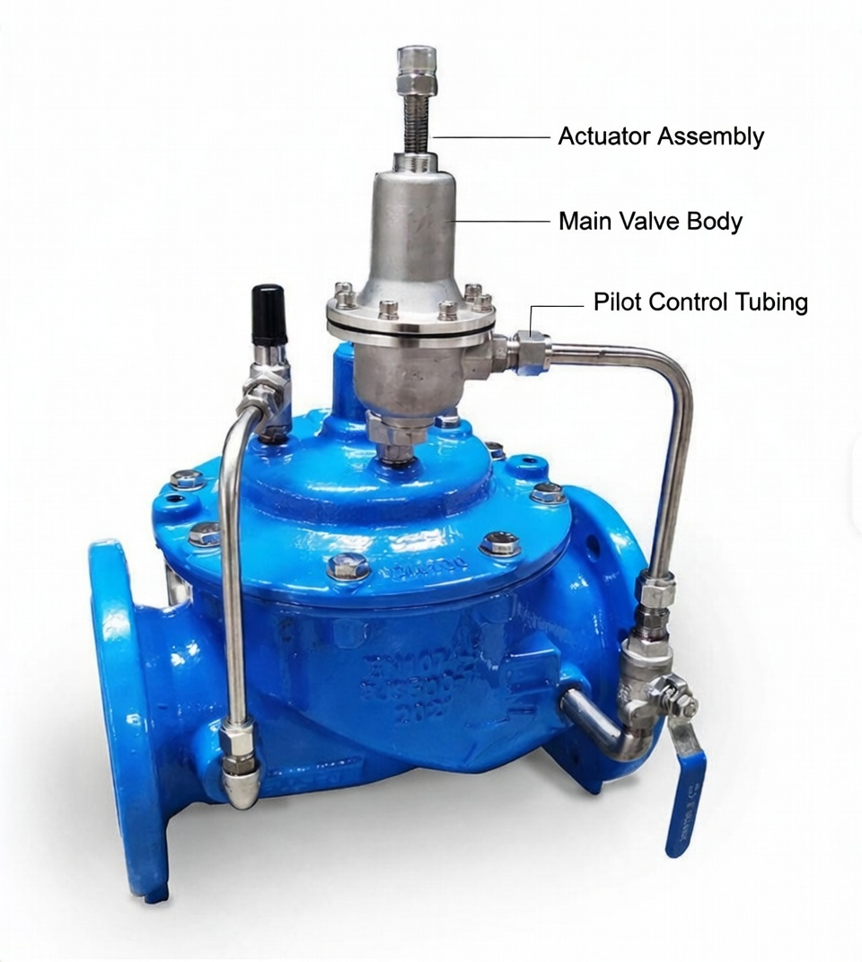
Design & Construction Diaphragm-actuated pilot operated design, Ductile iron body with blue epoxy coating, Stainless steel trim and seat Flanged connection, Sizes 2″ – 12″, Inlet pressure up to 300 psi
Performance Stable downstream pressure control, High flow capacity, Low hysteresis and minimal pressure droop Outlet pressure: 15 – 175 psi (adjustable), Wide flow range, Fast response to load changes
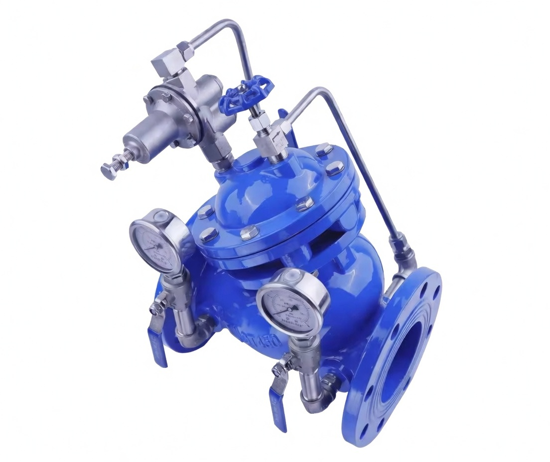
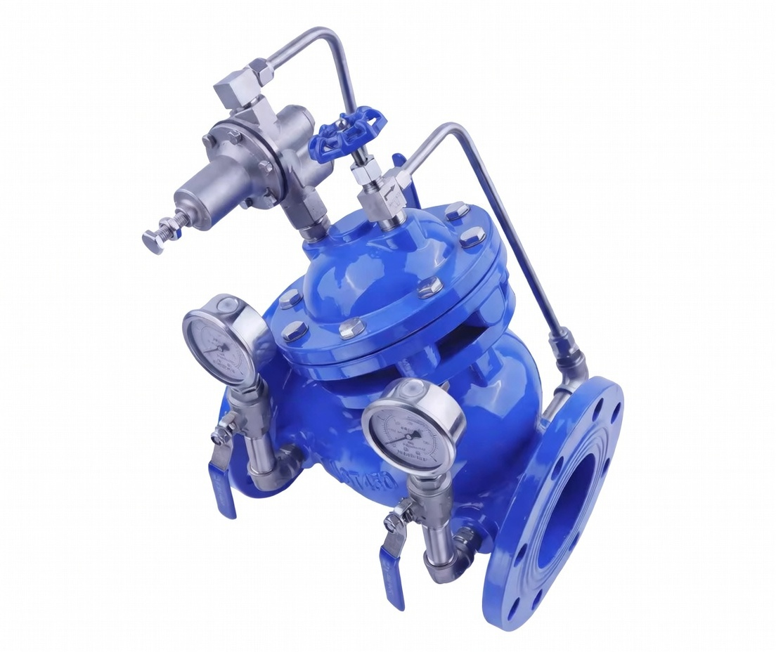
Monitoring & Control Adjustable pilot assembly, Dual pressure gauges (inlet & outlet), Easy set-point adjustment In-line maintenance capability, No special tools required for servicing
Applications Water supply networks, Irrigation systems, Fire protection systems, Hydraulic process lines, Pump stations, Industrial piping Ideal for protecting downstream equipment and maintaining consistent system pressure

Description

Category Key Features & Capabilities Critical Components
Pressure Regulation Precise downstream pressure control, High flow capacity, Stable regulation even with fluctuating inlet pressure or varying flow rates Main valve piston, Pilot valve, Sensing line, Adjustable spring
Hydraulic Control Pilot-operated design for accurate control, Remote pressure adjustment capability, Fast response to load changes Pilot control circuit, Orifice plates, Hydraulic dampener, Check valves
Applications Petrochemical, Power generation, Marine & offshore, Steel & heavy industry, Water distribution systems, Hydraulic presses & machinery Flanged or threaded connections, Custom materials for seawater or corrosive media
Performance High pressure reduction ratios (up to 20:1), Tight shut-off, Minimal pressure droop, Excellent stability under varying flows Hardened trim, Balanced piston design, Stainless steel pilot system
Safety & Certifications Over-pressure protection, Fail-safe operation, ATEX/IECEx for hazardous areas, PED & ASME compliant Rupture disc integration, Relief pilot, Lock-out devices, Position indicators

Key Benefits of Pilot Operated Hydraulic Control Pressure Reducing Valves

Category Key Benefits & Features
Superior Accuracy Maintains stable downstream pressure regardless of inlet fluctuations
Very low droop even at high flow rates
High sensitivity pilot control
High Reliability Rugged construction for extreme conditions
Long service life with minimal maintenance
Balanced design reduces wear
Energy Efficiency Low pressure loss across the valve
Optimized flow paths
Reduced energy consumption in hydraulic systems
Flexibility Wide pressure range adjustment
Remote control & automation ready
Multiple material options (Carbon Steel, Stainless, Duplex, Hastelloy)
Safety Built-in over-pressure protection
Fail-safe closing capability
Certified for hazardous and critical applications

Installation, Calibration & Support Services

Service Description
Installation & Commissioning Proper orientation, sensing line hookup, pilot adjustment, and full system integration & testing
Calibration & Setting Factory and on-site pressure setting, flow testing, and certification documentation
Maintenance & Support Periodic inspection, pilot overhaul, seal replacement, spare parts kits, and 24/7 emergency technical support

Additional information

Size

2", 3", 4", 6"

Materials of Construction

CS, DI, 304SS

Pressure Rating

150LB, 300LB, 600LB, 900LB, 1500LB

Specifications

Specification Details / Typical Values Notes
Valve Type Pilot-operated, diaphragm-actuated pressure reducing valve Hydraulic/pneumatic pilot control for accurate regulation
Body Material Ductile iron (ASTM A536 Grade 65-45-12 or equivalent) Epoxy-coated (interior/exterior) for corrosion resistance; blue paint common
Bonnet / Cover Ductile iron Diaphragm chamber dome-shaped
Trim / Seat Stainless steel seat and stem; Buna-N or EPDM resilient disc/seal Corrosion-resistant; options for seawater/service in premium versions
Diaphragm Nylon-reinforced Buna-N, EPDM, or natural rubber One-piece, rolling design for long life
End Connections Flanged (ANSI Class 150, PN16, or equivalent; raised/flat face) Bolt patterns match 4–12+ holes depending on size; common for 2″–8″ sizes
Nominal Sizes 2″ (DN50), 3″ (DN80), 4″ (DN100), 6″ (DN150), 8″ (DN200) common; up to 12″ possible Your photos suggest mid-to-large size (e.g., 4″–6″ based on flange scale)
Inlet Pressure (Max) 200–500 psi (14–35 bar); often 300–400 psi rated Varies by size/model; gauges show scales like 0–400/500 psi
Outlet Pressure Range Adjustable 15–175 psi (1–12 bar); common pilots: 30–165 psi or 50–175 psi Set via pilot screw/handwheel; factory often ~125 psi
Pressure Differential Min 10–20 psi (0.7–1.4 bar) required for proper operation Ensures pilot sensing and valve modulation
Flow Capacity High Cv; e.g., 2″: ~200–400 GPM, 4″: ~800–1500 GPM, 6″: ~2000–4000 GPM (varies) Depends on size and pressure drop; suitable for high-flow applications
Temperature Range 0–180°F (0–82°C) standard; up to 200°F+ with special seals For water/hydraulic fluids
Media Water, hydraulic oil, non-corrosive liquids Potable water versions may have NSF/ANSI 61 certification
Features Adjustable pilot, inlet/outlet gauges, isolation cocks on pilot lines, strainer in pilot circuit, optional speed controls Epoxy coating, in-line serviceability
Standards / Approvals Often AWWA, UL/FM (for fire models), ANSI flange drilling; epoxy per AWWA C550 Generic versions may lack full certifications
Installation Horizontal or vertical (arrow on body indicates flow direction) Pilot lines must be connected properly; gauges for monitoring

These are representative values for a typical pilot-operated pressure reducing valve (hydraulic control type, supplied by SRSINTL Direct. Contact SRSINTL Direct for exact model-specific details.

Maintenance Procedures

Important Safety Warnings

  • Always isolate the valve (close upstream and downstream isolation valves) and depressurize/bleed the system before any maintenance.
  • Release pressure from pilot lines, cover chamber, and body.
  • Wear appropriate PPE (gloves, eye protection, etc.).
  • Follow lockout/tagout procedures.
  • Refer to the specific IOM manual from SRSINTL Direct or valve markings for model-specific details.

Recommended Maintenance Schedule

Frequency Tasks
Daily / Weekly Visual inspection: Check for leaks, unusual noise, or damage to body, pilot lines, fittings, tubing, and gauges. Verify inlet/outlet pressures are stable.
Monthly Clean external surfaces. Inspect and clean Y-strainer / filter in pilot line. Check pilot system for air pockets or leaks. Test pilot adjustment (small ±5 psi change; observe downstream gauge response).
Quarterly / Every 3–6 Months Minor service: Inspect/clean pilot components (orifice, needle valves, strainer). Check main valve diaphragm (via cover vent test). Replace pilot diaphragm if worn/leaking. Bleed air from pilot lines.
Annually Full inspection: Test valve operation under flow. Check seat/disc for wear. Inspect main diaphragm, seals, and stem. Replace worn parts (e.g., Buna-N/EPDM diaphragm, O-rings). Calibrate gauges if needed.
Every 5–10 Years (or as needed) Major overhaul: Disassemble main valve (remove bonnet), inspect/replace diaphragm, disc/seat, stem, and internal trim. Reassemble with new seals/gaskets. Recommended in harsh conditions (high minerals, velocity, or corrosives).

Routine Visual & Functional Checks

  1. Confirm gauges read correctly and are not damaged (replace if fogged or stuck).
  2. Look for leaks at fittings, pilot tubing, bonnet, or body joints.
  3. Check pilot adjustment: Slowly turn pilot screw ± a few turns; downstream pressure should respond smoothly (no hunting or lag).
  4. Verify no air in pilot system (bleed via highest point if sluggish).
  5. Ensure isolation cocks/valves on pilot lines are open and functional.

Pilot System Cleaning & Minor Service

  • Isolate valve and depressurize.
  • Close pilot isolation cocks; remove/clean strainer/filter in pilot line (flush with clean water).
  • Inspect orifice/needle valves for blockages; clean gently (avoid enlarging holes).
  • Check pilot diaphragm for tears, hardening, or leaks (replace if dripping from vent or adjusting screw).
  • Reassemble, reopen cocks, and re-pressurize slowly. Test adjustment.

Main Valve Diaphragm / Seat Check (Annual or As Needed)

  • Isolate and depressurize valve.
  • Vent cover chamber (open bleed plug or highest fitting).
  • Observe: Valve should fully open; flow should stop once open (if continues → diaphragm leak → replace).
  • For full inspection: Remove bonnet (note torque sequence), inspect diaphragm/disc/stem for wear, scale, or damage. Clean/replace as needed. Reassemble with even torque.

General Tips & Best Practices

  • Keep accurate logs of inspections, adjustments, and parts replaced.
  • Use only compatible spare parts (e.g., Buna-N/EPDM diaphragms, stainless trim).
  • In hard water: More frequent strainer cleaning to prevent mineral buildup.
  • After any service: Flush system, slowly reopen valves, and verify stable pressure control.
  • Contact SRSINTL Direct for repair kits, exact diagrams, or if issues persist (e.g., hunting, failure to regulate, leaks).

Installation Procedures

Important Safety Warnings & Precautions

  • Installation must be performed by qualified personnel following local codes, standards (e.g., AWWA, NFPA if fire-rated), and manufacturer guidelines.
  • Depressurize and isolate the system before work. Lockout/tagout upstream/downstream lines.
  • Wear appropriate PPE (gloves, eye protection, hard hat, etc.).
  • Flush pipelines thoroughly before installation to remove debris, chips, scale, or foreign matter that could damage the valve or pilot system.
  • Do not lift the valve by pilot tubing, gauges, or trim—use slings/chains around the body or flange holes/eyebolts.
  • Ensure proper flow direction (arrow on body or inlet plate) and orientation (horizontal preferred, cover/diaphragm up; vertical acceptable if gauges readable and accessible).
  • Refer to SRSINTL Direct’s specific IOM (Installation, Operation, Maintenance) manual or valve markings for model details.

Pre-Installation Preparation

  1. Verify valve specifications match system requirements (size, pressure ratings, media, temperature, flange class—e.g., ANSI 150/PN16).
  2. Inspect valve for shipping damage; check pilot assembly, tubing, gauges, fittings, and seals are intact.
  3. Flush upstream piping thoroughly to remove debris (critical for pilot strainer and seat protection).
  4. Install isolation valves (gate/block) upstream and downstream of the PRV for future maintenance/isolation (recommended at least one pipe diameter apart).
  5. Optional but recommended: Install a strainer/Y-strainer upstream to protect the pilot circuit from particulates.
  6. Allow sufficient clearance around the valve for adjustments, pilot access, gauge reading, and disassembly (e.g., bonnet removal).

Physical Installation Steps

  1. Position the valve in the pipeline aligning flow direction with the arrow on the body/inlet plate or nameplate.
  2. Align flanges properly (raised face or flat face as per design); use appropriate gaskets (e.g., full-face rubber or ring-type for raised face).
  3. Install bolts/nuts in a crisscross/star pattern; tighten gradually and evenly to manufacturer torque specs (avoid over-tightening to prevent warping).
  4. Connect pilot tubing/fittings if not pre-assembled (ensure no kinks/twists; use thread sealant like Teflon tape on NPT threads).
  5. Install pressure gauges if not included (one upstream/inlet, one downstream/outlet for monitoring).
  6. Ensure pilot isolation cocks/valves (if present) are open; strainer in pilot line is clean/installed.
  7. Support piping as needed to prevent stress on the valve body.

Startup & Initial Adjustment Procedure

  1. Close downstream isolation valve; slowly open upstream isolation valve to fill the valve and pilot system (allow air to escape).
  2. Bleed air from highest points: Loosen pilot tubing fittings, cover vent plug (top of bonnet), and any high-point bleed valves until steady flow/no air bubbles.
  3. Once filled, slowly open downstream isolation valve to establish flow.
  4. Monitor inlet/outlet gauges; downstream pressure should stabilize.
  5. Adjust the pilot control (handwheel/screw on top pilot): Turn clockwise to increase downstream pressure, counterclockwise to decrease. Make small adjustments (e.g., 1/4–1/2 turn) while flow is present; allow system to stabilize between changes.
  6. Fine-tune for desired setpoint (e.g., 50–175 psi typical range; confirm with downstream gauge). Tighten lock nut/jam nut when set.
  7. If speed controls (opening/closing) are fitted, adjust them for smooth modulation (clockwise typically slows response).
  8. Cycle the system (open/close downstream valve) to verify stable regulation—no hunting, surging, or excessive lag.
  9. Check for leaks at flanges, fittings, pilot lines, bonnet, and body joints; tighten as needed.

General Tips & Best Practices

  • Horizontal installation with cover up is optimal for diaphragm life and air venting.
  • In vertical installations, ensure gauges are accessible and readable from a safe position.
  • For potable water systems, confirm NSF/ANSI 61 compliance if required.
  • Document initial setpoint, pressures, and observations for future reference.
  • If issues occur (e.g., no regulation, leaks, or failure to open/close), isolate valve, depressurize, and inspect pilot strainer, diaphragm, or seat.
  • Contact SRSINTL Direct for specific diagrams, torque values, repair kits, or troubleshooting if problems persist.

Advantages / Disadvantages

Category Description Typical Applications
Valve Type Diaphragm-actuated, Pilot Operated Pressure Reducing Valve Water distribution, Irrigation, Fire protection, Industrial process lines, Pump stations

Advantages

Category Key Advantages
Performance Excellent pressure stability with minimal droop
Handles wide flow variations effectively
High flow capacity with low pressure loss
Reliability & Durability Robust pilot-operated design for long service life
Corrosion-resistant epoxy coating and stainless trim
Proven in demanding water and process applications
Ease of Use Simple in-line maintenance
Dual gauges for easy monitoring
Adjustable pilot without removing valve from line
Cost Effectiveness Lower maintenance costs compared to direct-acting valves
Protects expensive downstream equipment
Energy efficient with low head loss

Disadvantages & Limitations

Category Key Limitations
Complexity More complex than direct-acting valves (pilot circuit)
Requires proper sensing line installation
More components to maintain
Cost Higher initial purchase price
More expensive spare parts than simpler valves
Sensitivity Pilot can be affected by dirty or contaminated fluid
May require strainers or filters upstream
Slower response in very small flow conditions
Installation Needs adequate straight pipe runs for best performance
Sensing line must be installed correctly
Not ideal for extremely compact spaces

Support & Maintenance Services

Service Description
Installation & Commissioning Correct orientation, sensing line setup, pressure adjustment, and system testing
Maintenance Pilot overhaul, diaphragm replacement, strainer cleaning, and performance verification
Technical Support Troubleshooting, spare parts supply, and 24/7 application engineering assistance

Applications

Pilot operated pressure reducing valves are ideal for systems requiring accurate, stable downstream pressure control under varying flow rates and inlet pressures.
Their high-capacity, diaphragm-actuated design makes them suitable for both clean water and industrial process applications.

Industry / Sector Key Applications Benefits in This Application
Water Supply & Distribution Municipal water networks, Zone pressure control, High-rise building water supply, Reservoir outlets Maintains constant outlet pressure, Prevents pipe bursts, Reduces water hammer
Irrigation & Agriculture Large-scale irrigation systems, Sprinkler & drip systems, Canal and pump station outlets Uniform pressure to all zones, Protects delicate irrigation equipment, Handles varying demand
Fire Protection Systems Fire hydrant pressure control, Sprinkler system feed, Standpipe systems, Pump room outlets Ensures adequate pressure for firefighting, Prevents over-pressurization of sprinklers
Industrial & Process Plants Petrochemical cooling water, Boiler feed water, Process water lines, HVAC systems Stable pressure for process equipment, Protects heat exchangers and pumps
Marine & Offshore Ballast systems, Seawater cooling lines, Firefighting on platforms, Shipboard water systems Corrosion-resistant design, Reliable operation in harsh marine environments
Power Generation Cooling water distribution, Demineralized water lines, Turbine auxiliary systems Precise pressure control for critical equipment, High reliability requirement

Why Choose Pilot Operated PRV for These Applications

Advantage Benefit
High Flow Capacity Suitable for large pipelines and high-demand systems
Stable Pressure Control Maintains set pressure even with large fluctuations in demand or inlet pressure
Durability Epoxy coated body and stainless trim handle aggressive water and industrial fluids
Low Maintenance In-line serviceable design reduces downtime

Installation, Calibration & Support Services

Service Description
Installation & Commissioning Flange connection, sensing line setup, pilot adjustment, and full system pressure testing
Calibration & Testing Field pressure setting and verification using inlet/outlet gauges
Maintenance & Support Scheduled inspections, diaphragm & pilot servicing, spare parts management, and 24/7 technical support

FAQs

Question Answer
What is a pilot operated pressure reducing valve? A pilot-operated pressure reducing valve uses a small pilot valve to control the opening and closing of the main valve. This design provides more accurate and stable downstream pressure control compared to direct-acting valves, especially in high-flow applications.
What is the typical outlet pressure range? Standard models typically regulate downstream pressure between 15–175 psi (1–12 bar). Higher pressure ranges are available upon request.
What materials are used? Body: Ductile iron with blue epoxy coating
Trim: Stainless steel
Diaphragm: EPDM or Nitrile
Pilot system: Stainless steel
What sizes are available? Common sizes range from 2″ to 12″ (DN50 to DN300). Larger sizes can be manufactured on request.
How does it differ from a direct-acting PRV? Pilot-operated valves offer higher accuracy, better stability at high flows, and lower pressure droop. They are preferred for larger pipes and critical applications, while direct-acting valves are simpler and better for small flows.
Does it require external power or air? No. The valve is fully self-acting and uses only the hydraulic energy of the line pressure to operate.
Can it be installed in any orientation? Horizontal installation with the pilot above the valve is recommended. Vertical installation is possible but may require special configuration.
How often does it need maintenance? Typically every 12–24 months depending on water quality. In clean water systems, maintenance intervals can be longer.

Still Have Questions?

Service Description
Technical Support Our engineers can help select the right valve size, pressure settings, and configuration for your specific application.
Site Visit & Consultation On-site assessment, pressure survey, and system analysis available.
Documentation Full technical data sheets, installation manuals, and material certificates provided.

Download

Drawings

Reviews

There are no reviews yet.


Only logged in customers who have purchased this product may leave a review.

You may also like