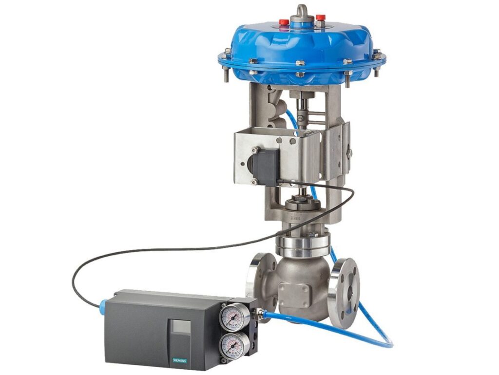
 The Control Valve Spec Form is used for each control valve. A buyer shall specify the process data for the following three flow conditions as a minimum. The flow conditions are normal Flow Rate, Maximum Flow Rate, and Minimum Flow Rate.
Goto Directly to Ordering Control Valves
Normal Flow Rate for Control Valve Spec Form
This flow condition is generally referred to as the design flow or material balance flow.
Maximum Flow Rate for Control Valve Spec Form
Also, when entering information on the Control Valve Spec Form, the flow condition shall be consistent with the plant or equipment operational maximum flow condition. The maximum flow condition is generally the governing case for the required maximum Cv capacity.
Minimum Flow Rate on Control Valve Spec Form
This flow condition shall be consistent with the plant turndown requirement or equipment turndown capability. The minimum flow condition generally subjects the control valve to the highest differential pressure condition. The minimum flow conditions are generally the governing case for the required trim performance.
In conclusion, the customer shall input information on the control valve spec form by also specifying the minimum and normal flow conditions for control valve services identified with “normally no flow” as well as the required flow conditions during non-normal plant operating conditions such as start-up, venting, depressurizing, etc.
Control Valve Sizing on Control Valve Spec form
Each control valve shall be sized and selected to provide reliable operation and control at the specified operating and design conditions. Control valve sizing shall generally be based on ISA S75.01, “Flow Equations for Sizing Control Valves”. Seller may deviate from the ISA formulas provided that the reason is detailed in the technical quotation.
For Gas Service Applications
Capacity (C) as a function of travel; confirmation by the Seller that the required rangeability can be met with the proposed control valve.
Also, noise calculations, including calculation basis and results, for each specified flow condition. This is so the Seller shall specify the maximum total inaccuracy (i.e., tolerance expressed in ±dBA for each noise calculation) and shall add this to his calculated noise level.
In addition, body and trim exit fluid velocity head calculations, including a number of discreet pressures drop stages required. They are required for each specified flow condition; the Seller is to also specify body and trim exit fluid velocities expressed in sonic velocity (Mach number).
For Liquid Service Applications
Capacity (C) as a function of travel; confirmation by the Seller that the required rangeability can be met with the proposed control valve.
Also, noise calculations, including calculation basis and results, for each specified flow condition; the Seller shall specify the maximum total inaccuracy (i.e., tolerance expressed in ±dBA for each noise calculation) and shall add this to his calculated noise level.
In addition, the cavitation index data and choked flow parameter data both as a function of travel. This is specific to the selected control valve and application. The Seller shall confirm in writing that the selected control valve eliminates cavitation damage.
Also, the Size Scale Effect (SSE) and Pressure Scale Effect (PSE) correction data for the cavitation index data.
Also, the body and trim exit fluid velocity calculations, including a number of discreet pressures drop stages required. This is for each specified flow condition.
Contact Us for more questions and Concerns
