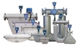
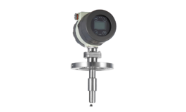
Description
Industries widely use a variable area flow meter, commonly known as a rotameter, to measure the flow rate of liquids and gases. This device relies on a simple yet effective principle of variable area measurement, where the cross-sectional area through which the fluid flows determine the flow rate. Here’s an in-depth exploration of the variable area flow meter, covering its working principle, components, applications, advantages, and maintenance.
Working Principle of a Variable Area Flow Meter
The core principle behind a variable area flow meter is relatively straightforward: it measures flow rate by observing the position of a float within a tapered tube. Manufacturers typically make the tube from glass or plastic, and the design ensures that its diameter increases progressively from bottom to top. This design is crucial because it allows the cross-sectional area through which the fluid flows to vary, hence the term “variable area.”
When fluid flows through the meter, it exerts an upward force on the float. The float rises until the area of the annular passage between the float and the tube wall is large enough to balance the upward force of the fluid. Furthermore, with the downward force of gravity acting on the float. The position of the float, therefore, corresponds directly to the flow rate: a higher float position indicates a higher flow rate and vice versa.
If you are need of other types of flow meters visit our flow meter product page
Components
Tapered Tube: The tube is the central component of the flowmeter and is usually made from materials such as glass or transparent plastic. Also, its tapered shape ensures that the cross-sectional area through which the fluid flows increase linearly with height.
Float: The float is positioned inside the tapered tube and is typically made from materials like stainless steel. Other materials used are plastic, or other non-corrosive materials. Additionally, it is designed to have a specific density that ensures it remains suspended within the fluid.
Scale: Attached to the outside of the tube is a graduated scale. The calibration process adjusts the scale to match the float’s position, providing a direct reading of the flow rate. Finally, scales can be linear or nonlinear depending on the design and application requirements.
Housing: The housing of the flowmeter encloses the tapered tube and float. This provides protection and facilitating the connection of the meter to the piping system. It often includes ports for input and output connections.
Flow Indicator: In some modern variable area flowmeters, digital displays or other electronic indicators are used to provide more precise readings. In addition, they will provide additional features such as alarms or data logging.
Types of Variable Area Flow meters
Variable area flowmeters come in various designs to cater to different applications:
Glass Rotameters: These are traditional flowmeters with a glass tube that allows for direct visual observation. This is direct observation of the float and flow rate. Moreover, they are ideal for applications requiring visual confirmation and have high accuracy.
Plastic Rotameters: Designed for corrosive or aggressive fluids, plastic rotameters offer a more affordable alternative to glass. Even as an alternative, it still provides accurate measurements.
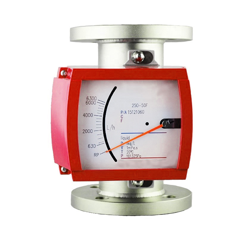
Metallic Rotameters: Used in high-pressure and high-temperature applications, metallic rotameters are durable and capable of handling more extreme conditions.
Electronic Rotameters: These advanced models integrate electronic sensors and transmitters to provide digital output and additional features. Additional features such as remote monitoring and data logging.
Conclusion
A variable area flowmeter, or rotameter, is a fundamental tool in flow measurement, known for its simplicity, reliability, and versatility. Also, by understanding its working principle, components, applications, advantages, and maintenance requirements, users can effectively utilize this device. They can use this device to monitor and control fluid flow in various industrial processes. Finally, regular maintenance and proper installation are key to ensuring optimal performance. In addition, it ensures longevity of the flowmeter, making it a valuable asset in numerous applications across different industries.
Specifications
The variable areas flow meter is available in various materials and in many different versions. Moreover, the sturdy all-metal flowmeter can be also used in applications with high pressures (up to 1500 psig), temperatures (-196…+400°C / -320…+752°F), or aggressive media. Also, it even allows installation in horizontal or fall pipes up to DN150 / 6″. After that, a special version for use in hygienic applications is also available. Finally, the Variable Area Flow Meter is intrinsically safe and explosion-proof.
Variable Area Flow Meter for liquids and gases
- Modular design: from mechanical indicator to 4…20 mA / HART®, and Totalizer
- Any installation position: Vertical, horizontal, or in fall pipes
- Flange: DN15…150 / 1⁄2…6″; also NPT, G, hygienic connections, etc.
- -196…+400°C / -320…+752°F; max. 1500 psig
- Simple, low-cost installation: Able to measure and display without an auxiliary power supply
- Unique modularity and serviceability: Limit switches, 2-wire 4…20mA, totalizer with LCD and pulse output,
- Universal ex-concept: Explosion-proof and intrinsically safe
- Various stainless steel and alloy sensor materials
- Optional stainless steel housing for corrosive atmospheres
- Ingress protection IP66 and IP68 / NEMA4X and NEMA6
- Full scale value for liquids: 10…120,000 l/h / 5…32,000 GPH
- Full scale value for gases: 0.7…2800 m3/h / 25…100,000 SCFH
- Turndown ratio 10:1 (optional 100:1)
- Accuracy: ±1.5%
- Optional hygienic design for use in the food and pharmaceutical industry
Installation
Installing a variable area flowmeter, commonly known as a rotameter, involves several key steps to ensure accurate flow measurement and reliable performance. Here’s a detailed guide to the installation procedures:
Planning and Preparation
Review Manufacturer’s Documentation: Carefully read the installation manual provided by the manufacturer. This manual includes specific instructions, installation requirements, and safety precautions for your particular model.
Gather Tools and Equipment: Collect all necessary tools and materials, including wrenches, mounting brackets, sealants, and any required fittings. Ensure you have the appropriate components for connecting the flowmeter to your system.
Select Installation Location: Choose a location that ensures accurate measurement and allows for easy access. The flowmeter should be installed in a straight section of the pipe with a stable flow profile to avoid disturbances that can affect accuracy. Ensure the location is free from excessive vibrations, heat, or corrosive environments that could damage the flowmeter.
System Preparation
Shut Down the System: Before installing the flowmeter, shut down the system and depressurize the pipeline. This step ensures safety and prevents any accidental spills or leaks during installation.
Prepare the Installation Site: Clean the pipe or connection point where the flowmeter will be installed. Remove any debris, rust, or old sealant to ensure a good seal and accurate measurement.
Installing the Flowmeter
Check Orientation and Alignment: Ensure that the flowmeter is oriented correctly according to the manufacturer’s instructions. Most variable area flowmeters need to be installed vertically with the flow direction indicated by an arrow on the device. Proper alignment is crucial for accurate readings.
Install the Flowmeter:
Threaded Connections: If the flowmeter uses threaded connections, apply a suitable thread sealant to prevent leaks. Screw the flowmeter into the pipe or fitting and tighten it securely with a wrench. Avoid over-tightening, which can damage the flowmeter or pipe.
Flanged Connections: For flowmeters with flanged connections, align the flowmeter with the pipe flanges and place any necessary gaskets. Secure the flowmeter with bolts, tightening them evenly in a cross pattern to ensure a uniform seal.
Verify the Installation: Double-check that the flowmeter is securely installed and that all connections are tight. Ensure the flowmeter is aligned properly with the pipe and that there are no obstructions or misalignments.
Connecting and Testing
Reconnect the System: Once the flowmeter is installed, reconnect the system and gradually reintroduce pressure. Check for any leaks around the flowmeter and connections.
Test the Flowmeter: Perform a test run to ensure the flowmeter operates correctly. Observe the float’s position to verify that it moves freely and accurately reflects the flow rate. Compare the readings with expected values to ensure proper calibration.
Check for Proper Operation: Monitor the flowmeter during the test run to ensure it is functioning properly and that the readings are stable. Look for any signs of interference or instability in the float’s position.
Final Checks and Documentation
Inspect the Installation: Conduct a final inspection to ensure that the flowmeter is correctly installed, secure, and functioning as expected. Verify that the flowmeter is free from leaks and that the connections are tight.
Document the Installation: Record all relevant installation details, including the location of the flowmeter, connection types, calibration settings, and any observations from the testing phase. This documentation is useful for future reference and maintenance.
Provide Training: If necessary, provide training to relevant personnel on how to operate and maintain the flowmeter. Ensure they understand how to read the flowmeter and what actions to take in case of any issues.
Ongoing Maintenance and Monitoring
Schedule Regular Inspections: Plan regular inspections to check the condition of the flowmeter and its performance. Inspect for any signs of wear, damage, or calibration drift.
Monitor Performance: Continuously monitor the performance of the flowmeter to ensure it provides accurate measurements. Address any issues promptly to maintain optimal operation.
By following these installation procedures, you can ensure that your variable area flowmeter is set up correctly and functions reliably, providing accurate flow measurements for your system. Regular maintenance and proper installation are key to the long-term performance and accuracy of the flowmeter.
Maintenance
Maintaining a variable area flowmeter, or rotameter, is crucial to ensure its accuracy, reliability, and longevity. Proper maintenance helps prevent issues such as drift in measurements, mechanical failures, or inaccurate readings. Below is a comprehensive guide to the maintenance procedures for a variable area flowmeter:
Routine Inspections
Visual Inspection: Regularly inspect the flowmeter for any physical damage, such as cracks in the glass or plastic tube, corrosion, or loose fittings. Ensure that the flowmeter is securely mounted and that no components are missing or damaged.
Float and Tube Condition: Check the condition of the float and the interior of the tube. Look for any signs of wear, buildup, or contamination that could affect the float’s movement or the accuracy of measurements. Ensure the float moves freely and is not obstructed.
Connection Integrity: Verify that all connections to the flowmeter, including threaded or flanged connections, are secure and free from leaks. Check that seals and gaskets are in good condition and replace them if necessary.
Cleaning
Schedule Cleaning: Depending on the operating environment and the type of fluids measured, schedule regular cleaning to prevent buildup of debris or contaminants that could affect performance.
Cleaning Procedure:
Turn Off and Depressurize: Before cleaning, turn off the system and ensure that the pipeline is depressurized to prevent accidents and ensure safety.
Remove the Flowmeter: If necessary, carefully remove the flowmeter from its installation point, following proper procedures to avoid damage.
Clean the Flowmeter: Use appropriate cleaning agents based on the fluid being measured. For glass or plastic tubes, use a non-abrasive cleaner and a soft cloth. Avoid harsh chemicals or abrasive materials that could damage the flowmeter.
Inspect and Reinstall: After cleaning, inspect the flowmeter for any damage. Reinstall the flowmeter, ensuring that all connections are secure, and the device is properly aligned.
Calibration
Regular Calibration: Follow the manufacturer’s recommendations for calibration frequency. Regular calibration is essential to ensure the accuracy of flow measurements.
Calibration Procedure:
Verify Calibration Schedule: Check the recommended calibration intervals specified by the manufacturer and adhere to them.
Use Calibration Standards: Perform calibration using accurate flow standards or reference materials. This ensures that the flowmeter provides accurate readings.
Adjust Settings: If the calibration process reveals discrepancies, adjust the flowmeter’s settings as necessary to match the reference standards.
Battery and Power Management
Check Power Sources: For battery-powered flowmeters, regularly inspect the battery levels and replace batteries before they are fully depleted. Ensure that the power source meets the flowmeter’s requirements.
Inspect Power Connections: Ensure that all power connections are secure and free from corrosion or damage. For wired power sources, check that connections are intact and reliable.
Firmware and Software Updates
Check for Updates: If the flowmeter is equipped with electronic components or digital indicators, periodically check for firmware or software updates from the manufacturer.
Install Updates: Follow the manufacturer’s instructions to download and apply updates. Schedule updates during maintenance windows to minimize operational disruption.
Data Management
Review Data Logs: Regularly review data logs, if available, for any anomalies or trends that might indicate issues with the flowmeter. This helps in early detection of potential problems.
Backup Data: Ensure that data is backed up regularly, especially if the flowmeter integrates with digital systems or data management platforms.
Troubleshooting
Address Performance Issues: If the flowmeter exhibits irregular performance or inaccuracies, follow the troubleshooting steps provided by the manufacturer. Common issues may include signal interference, mechanical obstruction, or calibration drift.
Contact Support: For persistent or complex issues, contact the manufacturer’s technical support team for further assistance and guidance.
Documentation
Record Maintenance Activities: Document all maintenance activities, including inspections, cleaning, calibrations, and repairs. Keeping detailed records helps track the flowmeter’s history and plan future maintenance.
Update Maintenance Logs: Maintain updated logs of any changes or updates made to the flowmeter’s configuration, software, or hardware. This documentation is crucial for ongoing maintenance and troubleshooting.
Training and Best Practices
Train Personnel: Ensure that all personnel responsible for operating or maintaining the flowmeter are properly trained. They should be familiar with the maintenance procedures and understand how to operate the flowmeter effectively.
Follow Best Practices: Adhere to industry best practices for the care and handling of flowmeters. Avoid exposing the flowmeter to harsh conditions or operating outside its specified limits to prevent damage and ensure longevity.
Safety Considerations
Safety Precautions: Always follow safety precautions during maintenance. Wear appropriate protective gear, ensure the system is safely shut down, and handle the flowmeter carefully to avoid accidents.
Handling and Storage: Properly handle and store the flowmeter to prevent physical damage. Avoid dropping or subjecting it to impacts that could affect its performance.
By adhering to these maintenance procedures, you can ensure that your variable area flowmeter remains in optimal condition, providing accurate and reliable flow measurements. Regular maintenance helps extend the life of the device and ensures that it continues to perform effectively in various industrial applications.
Q&A
A Q&A, or Question and Answer session, is a common format used to exchange information and address specific queries related to a particular topic. In the context of Variable Area Flow Meters, a Q&A session could involve individuals asking questions about the functioning, installation, calibration, troubleshooting, and other aspects of Variable Area Flow Meters.
In a Q&A, experts or knowledgeable individuals provide answers to these questions and share insights, best practices, and technical knowledge related to Variable Area Flow Meters. This can help attendees gain a better understanding of variable area flow meters and address any concerns or uncertainties they may have.
Q: What are Q&A Variable Area Flow Meters?
A: Variable area flow meters are a type of flow meter that uses a tapered tube and a float to measure the flow rate of a fluid. The flow rate is indicated by the position of the float within the tube, which varies with changes in the fluid flow rate.
Q: How does a work?
A: Variable area flow meters work by using a tapered tube with a larger opening at the bottom and a smaller opening at the top. As the fluid flows through the tube, it pushes the float upwards. This creates a larger area for the fluid to flow through. The position of the float within the tube indicates the flow rate of the fluid.
Q: What are the advantages of using a variable area flow meter?
A: Some advantages of using a variable area flow meter include:
-
- Simple design with no moving parts, which reduces maintenance requirements and increases reliability
-
- Can be used for a wide range of fluid types, including liquids and gases
-
- Can measure both high and low flow rates
-
- Can be used in both horizontal and vertical pipe orientations
-
- Can provide a visual indication of the flow rate
Q: What are some common applications for Q&A Variable Area Flow Meters?
A: Variable area flow meters are commonly used in industrial and laboratory settings for measuring the flow of gases and liquids in pipes and tubing. They are often used in applications where simplicity and low cost are more important than high accuracy. Accuracy requirements such as in HVAC systems, water treatment plants, and chemical processing.
Q: What are some potential limitations or drawbacks of using a variable area flow meter?
A: Some potential limitations of using a variable area flow meter include:
-
- Lower accuracy compared to other types of flow meters, such as electromagnetic or ultrasonic flow meters
-
- Limited to lower flow rates compared to other types of flow meters
-
- Can be affected by changes in fluid viscosity, density, and temperature, which can affect the accuracy of the meter
-
- Can be more prone to errors if the float becomes stuck or if the tube becomes dirty or clogged
Q: How can variable area flow meters be calibrated?
A: Variable area flow meters can be calibrated using a reference standard, such as a calibrated container or a more accurate flow meter. The fluid is passed through the variable area flow meter and the reference standard at the same time. After, the readings from both devices are compared to determine any differences in accuracy. The meter can then be adjusted accordingly to improve its accuracy.
Q: What materials are variable area flow meters typically made from?
A: Variable area flow meters can be made from a variety of materials depending on the application. This includes metals such as stainless steel, brass, and aluminum, as well as plastics such as PVC, PTFE, and acrylic. The choice of material depends on factors such as the type of fluid being measured. Other factors consider the temperature and pressure of the fluid and the required level of accuracy.
Q: How does the shape and size of the tapered tube affect the accuracy of a variable area flow meter?
A: The shape and size of the tapered tube can affect the accuracy of a variable area flow meter. it assists, as it determines the shape and size of the flow area and therefore the position of the float. A larger taper angle can provide better accuracy at lower flow rates. A smaller taper angle can provide better accuracy at higher flow rates. The length of the tube can also affect the accuracy as well. A long tube can provide a larger range of flow rates. It may be more susceptible to errors from dirt or debris build-up.
Q: Can variable area flow meters be used in hazardous or corrosive environments?
A: Variable area flow meters can be designed and constructed to be used in hazardous or corrosive environments. Also, by using materials such as stainless steel or special coatings to resist corrosion. An explosion-proof housings and other safety features to prevent the risk of fires or explosions.
Q: What is the typical accuracy of a variable area flow meter?
A: The typical accuracy of a variable area flow meter depends on factors such as the flow range. Other factors consider the size and shape of the tube, and the quality of the float. In general, the accuracy of a variable area flow meter can range from 2% to 10% of the full-scale flow rate.
Buy Variable Area Flow Meters?
Advantages / Disadvantages
Advantages
Simple Design: Variable Area Flow Meters have a straightforward design that is easy to install and operate.
Wide Flow Range: They can handle a wide range of flow rates, making them versatile for different applications.
No Power Requirement: They do not require an external power source to operate, making them cost-effective and suitable for areas with limited power supply.
Easy Visual Readings: The variable area (often a float) inside the meter provides a clear visual indication of the flow rate. The presence of a float and scale affords an immediate visual indication of the flow rate, allowing for quick and intuitive monitoring and adjustment of the flow.
Reliable: These meters are known for their reliability and stability in measuring flow rates over time. With their straightforward design, variable area flow meters are easy to install, operate, and maintain. They have few moving parts, reducing the risk of mechanical failures, and are known for their long-term reliability.
Compatibility: Variable area flow meters are compatible with a vast range of fluids, including aggressive and corrosive ones. The choice of tube material can be tailored to suit the specific application, ensuring compatibility with the fluid being measured.
Wide Rangeability Variable area flow meters offer excellent rangeability, allowing them to measure flow rates across a wide span. They can accurately measure both high and low flow rates, making them versatile for various applications.
Disadvantages
Pressure Drop: Variable Area Flow Meters can cause a pressure drop in the system due to the constriction of flow, affecting the overall system efficiency.
Accuracy: While they are generally reliable, Variable Area Flow Meters may not be as precise as some other types of flow meters, especially in high-precision applications.
Limited to Clean Fluids: They may not be suitable for fluids with particles or impurities that could affect the movement of the float.
Subject to Gravity: In some cases, the orientation of the meter can affect the accuracy of the readings, especially in vertical installations.
Size Limitations: Variable Area Flow Meters may not be suitable for large flow rates or very small flow rates, depending on the specific design and size of the meter.
These points can help in understanding the practical aspects of using a Variable Area Flow Meter in various applications.
Applications
Process Industries Variable area flow meters find extensive use in process industries, such as chemical, pharmaceutical, and food processing, where the accurate measurement and control of fluid flow rates are critical.
Laboratory and Research
Their simplicity, reliability, and visual flow indication make variable area flow meters a popular choice in laboratories and research facilities. They are often utilized for experimentation, calibration, and general flow rate measurements.
HVAC Systems
These flow meters are also employed in heating, ventilation, and air conditioning (HVAC) systems to monitor and control fluid flows for optimal system performance and energy efficiency.
Chemical and other process industries:
- Additives (e.g. catalysts, foam inhibitors, emulsifiers)
- Acids, bases, phosgene, and other chlorides substances, sulfuric substances
- Condensate and cooling water
- Nitrogen inertia of vessels and tanks
- Sample flow monitoring for process analysis
- Gas sparging in liquids
Oil and gas industry
- Injection skids for corrosion-, scale- and hydrate-inhibitors
- Nitrogen, flue gases, etc.
- In addition, Emulsifiers
Oil and gas industries rely on variable area flow meters for various applications, including measuring flow rates in pipelines, monitoring additive injection, and managing the flow of gases and liquids.
Machinery and apparatus
- Gas seal monitoring for compressors
- Also, Coolants and cooling water, lubricants, air supply
- Dry-run prevention of pumps
- Gas and oil measurement for industrial furnaces
Pharmaceutical industry
- Demineralized water, alcohol, solvents, insulin, etc.
- Also, Cleaning agents
- Air measurement in clean rooms
Food and beverage industry
- Vegetable oil, drinking water, milk, carbon dioxide
- Cleaning agents
Water and wastewater industry
- Oxygen sparging into aeration basins
- Air injection to reduce iron content
Conventional and nuclear power industry
- Heavy water, borated water, tritium etc.
- Hydrazine
- Sulfuric acid
- Phosphate, nitrogen, hydrogen, Sulfur
- Purified water, saline water, etc.
- Steam, air, gases, boiler washing water etc.
- Diesel, return fuel oil flows, etc.
Drawings

